Project Gallery
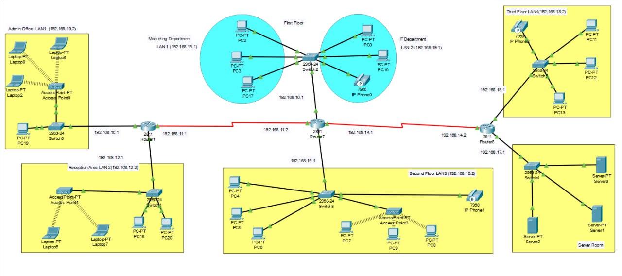
Project Overview
🏨 Hotel Network Project Overview
🔹 Objective:
The objective of this project is to design and implement a hotel network infrastructure using Cisco Packet Tracer. The key components include:
- Implementation of multiple VLANs to separate departments.
- Wireless Access Points to enable mobility for laptops and mobile devices.
- IP Phones (VoIP) for efficient voice communication.
- DHCP configuration for automatic IP address assignment.
- Routers and switches to ensure full network interconnectivity.
- A hierarchical topology that supports future scalability and maintenance.
🌐 Network Zones & IP Subnets
Below is the structure of different departments, VLANs, and IP subnets used in the project:
Admin Office: LAN1 — 192.168.10.0/24 — Laptops, PC, Access Point
Reception Area: LAN2 — 192.168.12.0/24 — PCs, Access Point
Marketing Department: LAN1 — 192.168.13.0/24 — PCs
IT Department: LAN2 — 192.168.19.0/24 — PCs, IP Phone
Second Floor: LAN3 — 192.168.15.0/24 — PCs, Access Point, IP Phone
Third Floor: LAN4 — 192.168.18.0/24 — PCs, IP Phone
Server Room: Internal LAN — 192.168.17.0/24 — Servers
🔗 Connectivity
- Each VLAN is connected via dedicated switches and linked to a central router.
- Routers (Cisco 2811) are used to connect different departments and floors.
- DHCP is configured to automatically assign IP addresses to devices.
- Wireless access is available in the Admin Office, Reception Area, and Second Floor.
- VoIP phones are installed in the IT Department, Second Floor, and Third Floor for internal communication.
✅ Key Technologies Used
VLAN: For logical network segmentation.
DHCP: Automatically assigns IP addresses to devices.
Wireless Access Points: Enables mobility and laptop connectivity.
VoIP (IP Phones): Facilitates internal voice communication.
Switch (Cisco 2950): Provides LAN connectivity within departments.
Router (Cisco 2811): Handles routing between VLANs and overall network connectivity.
🔗 Network Interface IP Addresses
- 192.168.10.2 (Admin Office LAN1)
- 192.168.13.1 (Marketing Department LAN 1)
- 192.168.10.1 (Connection between Switch0 and Router1)
- 192.168.11.1 (Router1 interface)
- 192.168.12.1 (Reception Area LAN 2)
- 192.168.12.2 (Reception Area LAN 2)
- 192.168.11.2 (Router7 interface)
- 192.168.16.1 (First Floor network segment)
- 192.168.19.1 (IT Department LAN 2)
- 192.168.18.1 (Connection between Switch5 and Router8)
- 192.168.14.1 (Connection between Router7 and Router8)
- 192.168.14.2 (Connection between Router8 and Switch4)
- 192.168.17.1 (Router8 interface)
- 192.168.15.1 (Second Floor LAN3 network segment)
- 192.168.15.2 (Second Floor LAN3)
🧰 VLAN Groups
- VLAN 10 – Admin Office
- VLAN 12 – Reception
- VLAN 13 – Marketing
- VLAN 15 – Second Floor
- VLAN 18 – Third Floor
- VLAN 19 – IT Dept
- VLAN 17 – Server Room
Network Technologies
| Technology | Purpose |
|---|---|
| VLAN | Logical segmentation of network |
| DHCP | Automatic IP address assignment |
| Wireless | Wireless connectivity for users |
| VoIP | Internal voice communication |
| Switch (2950) | Device-to-device LAN connection |
| Router (2811) | Routing between VLANs |
Our Team
Mubas Sera Noon
DHCP and Wireless Network
Md Ibna Labid
VoIP Configuration
Raiyan Jahan
Network Design & IP Addressing
Mst. Tabassum Binte Zia Prova
VLAN Configuration & Switching
Fahim Montasir
Server Room & Final Testing